Learning how to read construction plans can feel confusing at first. A full plan set may have dozens or even hundreds of drawings, symbols, notes, scales, dimensions, schedules, and details. For beginners, it is easy to open a PDF and feel lost before reaching the floor plan.
- Click the plan, follow the sheets, and learn what to check next.
- What Are Construction Plans and Blueprints?
- Before You Start: Understand the Plan Set
- Step 1: Read the Title Block and Sheet Index
- Step 2: Review General Notes, Legends, and Abbreviations
- Step 3: Check the Site Plan
- Step 4: Read the Floor Plans
- Step 5: Understand Elevations and Sections
- Step 6: Follow Callouts to Detail Drawings
- Step 7: Read Structural, Mechanical, Electrical, and Plumbing Sheets
- Step 8: Use Scale, Dimensions, and Grid Lines Correctly
- Step 9: Cross-Check Notes, Schedules, and Specifications
- Common Blueprint Symbols and Line Types
- Worked Example: Reading a Door Opening
- Common Mistakes When Reading Construction Plans
- Practice Workflow: The First 10 Minutes With a Plan Set
- Trade-Specific Shortcuts
- What to Do When Drawings Conflict
- FAQs
- What is the first thing to look at when reading construction plans?
- How do you read blueprint symbols?
- What does the title block tell you?
- How do you use scale on construction drawings?
- What is the difference between a floor plan, elevation, and section?
- How do you read dimensions on construction plans?
- What are general notes in construction drawings?
- What are MEP drawings?
- How can beginners practice reading blueprints?
- What should you do if construction drawings conflict?
- Final Thoughts
The good news is that construction drawings become much easier once you follow a clear order.
You do not read building plans like a normal book. You read them like a connected system. A floor plan may show where a wall goes, but the wall type may be explained in a schedule. A section may show how tall something is, but the detail drawing may explain how it is built. A door tag on one sheet may send you to a door schedule on another sheet.
That is the main idea behind blueprint reading: do not guess from one drawing. Follow the references.
This guide explains how to read construction plans step by step, including title blocks, sheet indexes, legends, floor plans, site plans, elevations, sections, scale, dimensions, symbols, MEP drawings, schedules, specifications, and common mistakes.
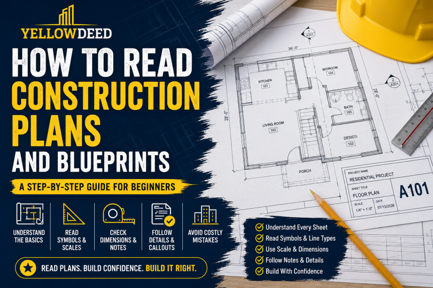
Click the plan, follow the sheets, and learn what to check next.
This layout helps beginners understand construction plans, title blocks, symbols, dimensions, callouts, details, schedules, and when to ask for clarification.
103
101
104
105
106
Title Block
The title block tells you the sheet number, sheet title, scale, issue date, project name, consultant, and revision status. Always check this before trusting the drawing.
What Are Construction Plans and Blueprints?
Construction plans are the drawings and documents used to explain how a project should be built. They may also be called construction drawings, blueprints, building plans, or construction documents.
Today, most blueprints are digital PDFs instead of old blue paper drawings. But the plan-reading principles are the same. You still need to understand the sheet set, title block, scale, symbols, notes, dimensions, and details before making field decisions.
A typical plan set may include:
| Sheet type | What it usually shows |
|---|---|
| Cover sheet | Project name, drawing list, codes, contacts, and issue date |
| Site plan | Property lines, building location, utilities, access, grading, and north arrow |
| Floor plans | Walls, rooms, doors, windows, dimensions, and layout |
| Elevations | Exterior or interior vertical views |
| Sections | Cut-through views that show height, structure, and assemblies |
| Details | Enlarged drawings for specific construction conditions |
| Schedules | Doors, windows, finishes, equipment, fixtures, and materials |
| Structural drawings | Foundations, framing, beams, columns, slabs, and structural notes |
| Mechanical drawings | HVAC equipment, ducts, vents, and mechanical systems |
| Electrical drawings | Lighting, outlets, panels, circuits, and power systems |
| Plumbing drawings | Water lines, drains, fixtures, and plumbing systems |
| Specifications | Written requirements for materials, products, workmanship, and standards |
The drawings tell you where things go. The specifications often tell you what products, materials, and standards apply.
Before You Start: Understand the Plan Set
A common beginner mistake is jumping straight into the floor plans.
That is understandable because floor plans look the most familiar. They show rooms, walls, doors, and windows. But if you skip the cover sheet, sheet index, general notes, legends, and abbreviations, you may misread the drawings before you even start.
A construction plan set is organized by discipline. Architectural drawings may show layout and design intent. Structural drawings show foundations and framing. Mechanical, electrical, and plumbing sheets show building systems. Civil drawings show site work. Landscape drawings show planting, hardscape, and outdoor areas. Fire protection drawings may show sprinklers and life-safety systems.
Each sheet has a purpose. The goal is to understand how the sheets connect.
Step 1: Read the Title Block and Sheet Index
The title block is usually found along the bottom or side of each sheet. It tells you basic information about that drawing.
A title block may include:
- Project name
- Project address
- Architect or engineer
- Sheet title
- Sheet number
- Scale
- Date
- Revision information
- Drawing issue
- Consultant name
- Approval or stamp information
The sheet number helps you understand where the drawing belongs. For example, architectural sheets may start with A, structural sheets with S, mechanical sheets with M, electrical sheets with E, and plumbing sheets with P.
The sheet index is usually found near the front of the plan set. It lists all drawings included in the project.
Before reading details, scan the sheet index and ask:
- Which disciplines are included?
- Are there architectural drawings?
- Are there structural drawings?
- Are mechanical, electrical, and plumbing sheets included?
- Are there civil, landscape, or fire protection sheets?
- What is the latest issue date?
- Are there revised sheets?
This gives you the map before you read the actual plans.
Step 2: Review General Notes, Legends, and Abbreviations
General notes explain rules that apply across the project. They may include code references, construction standards, safety requirements, installation notes, material requirements, and coordination instructions.
Do not ignore general notes. They often include information that does not appear directly on the plan view.
A legend explains symbols, line types, tags, and abbreviations. For example, a dashed line may mean overhead work, hidden work, demolition, or something else depending on the drawing. The legend tells you what it means on that project.
Common items in this section include:
| Item | Why it matters |
|---|---|
| Legend | Explains symbols and line types |
| Abbreviations | Defines short forms used on drawings |
| General notes | Gives project-wide rules and requirements |
| Symbol key | Explains door tags, window tags, section marks, and callouts |
| Revision notes | Shows what changed in updated drawings |
Many blueprint symbols look similar. Never assume a symbol means the same thing on every project. Always check the legend.
Step 3: Check the Site Plan
The site plan shows how the building sits on the property.
A site plan may include:
- Property lines
- Building footprint
- Setbacks
- Driveways
- Parking
- Sidewalks
- Utilities
- Easements
- Grading
- Drainage
- Landscaping
- Access points
- North arrow
- Adjacent roads or structures
The north arrow helps you understand orientation. This matters when comparing the site plan with floor plans, elevations, shadows, entrances, and exterior features.
For contractors, the site plan is especially important because it affects access, staging, utilities, drainage, excavation, and coordination with other trades.
If you are a homeowner reading building plans for a renovation or new build, the site plan helps you understand where the structure sits and how it relates to the lot.
Step 4: Read the Floor Plans
Floor plans are plan view drawings. That means you are looking down from above, as if the building was cut horizontally and you are viewing the layout from the top.
A floor plan usually shows:
- Room names
- Walls
- Doors and windows
- Door swings
- Dimensions
- Grid lines
- Room tags
- Wall types
- Stairs
- Fixtures
- Cabinetry
- Equipment
- Elevation markers
- Section marks
- Detail callouts
Start by understanding the overall layout. Do not focus on tiny details right away.
Look for the main spaces first. Then find walls, doors, windows, corridors, stairs, and key dimensions. After that, start following tags and callouts.
A door tag might say D-102. That means the door is identified on the plan, but the full door information is probably in the door schedule. A wall type tag might refer to a wall assembly schedule. A section marker may point you to another sheet that shows how the wall, floor, or roof is built vertically.
Floor plans show location. They do not always show the full construction requirement.
Step 5: Understand Elevations and Sections
Elevations show vertical views of a building or space.
An exterior elevation shows what the outside of the building looks like from one direction. It may show doors, windows, cladding, roof lines, exterior materials, heights, and finished grades.
An interior elevation shows a wall inside a room. It may show cabinets, counters, tile layouts, fixtures, wall panels, equipment, shelving, or special finishes.
Sections are different. A section cuts through the building to show what is inside the assembly. It helps you understand height, floor levels, ceiling heights, wall assemblies, roof conditions, stairs, foundations, and structural relationships.
A simple way to remember:
| Drawing | What it answers |
|---|---|
| Floor plan | Where is it located? |
| Elevation | What does it look like vertically? |
| Section | How does it work through the building? |
| Detail | How is this specific part built? |
If a plan shows a stair, the section may explain floor-to-floor height. If an elevation shows a window, the detail may explain flashing, trim, or wall assembly.
Step 6: Follow Callouts to Detail Drawings
Callouts are one of the most important parts of construction drawings.
A callout points from a larger drawing to a more specific detail. It may show a circle, bubble, or tag with a detail number and sheet number.
For example, a callout might show:
Detail 5 / A-501
That usually means detail number 5 on sheet A-501.
Do not guess from the main plan if a callout exists. The detail drawing is there because the designer wants you to see more information.
Detail drawings may show:
- Wall assemblies
- Waterproofing
- Flashing
- Roof edges
- Foundation connections
- Door and window conditions
- Stair details
- Cabinet details
- Structural connections
- Finish transitions
- Material layers
Details are where costly mistakes often happen. A floor plan may only show a line, but the detail explains the actual construction.
Step 7: Read Structural, Mechanical, Electrical, and Plumbing Sheets
After you understand the architectural drawings, cross-check the trade drawings.
Structural Drawings
Structural drawings show how the building is supported. They may include foundation plans, framing plans, beams, columns, slabs, shear walls, roof framing, structural notes, and connection details.
Framers, concrete crews, steel contractors, and general contractors should read these carefully. Structural drawings often control critical dimensions and load-bearing elements.
Mechanical Drawings
Mechanical drawings show HVAC systems. They may include ductwork, equipment locations, diffusers, vents, exhaust fans, thermostats, and mechanical schedules.
HVAC contractors should compare mechanical drawings with reflected ceiling plans, structural framing, and architectural ceiling heights before installation.
Electrical Drawings
Electrical drawings show lighting, outlets, switches, panels, circuits, fire alarm devices, low-voltage systems, and power requirements.
Electricians need to coordinate these drawings with architectural plans, ceiling plans, equipment schedules, and code requirements.
Plumbing Drawings
Plumbing drawings show water supply, drains, vents, fixtures, equipment, risers, and pipe routing.
Plumbers should check fixture locations against floor plans, wall types, structural elements, and ceiling spaces.
MEP Drawings
MEP drawings are mechanical, electrical, and plumbing drawings together. These sheets must be coordinated with the architectural and structural drawings. If they conflict, do not guess. Raise an RFI or ask the architect, engineer, project manager, or general contractor.
Step 8: Use Scale, Dimensions, and Grid Lines Correctly
Scale tells you how the drawing relates to real size. For example, a drawing may be shown at 1/4 inch equals 1 foot.
A scale ruler or architect scale can help you measure printed drawings, but be careful. Many drawings are viewed digitally now, and PDF scaling can be wrong if printed incorrectly.
A key rule: written dimensions usually control over scaled measurements.
That means if a wall is labeled as 12 feet long, use the written dimension. Do not measure the PDF and assume your measurement is better.
Look for:
- Dimension lines
- Grid lines
- Centerlines
- Finished face dimensions
- Rough opening dimensions
- Overall dimensions
- Interior room dimensions
- Elevation heights
Grid lines are often used to locate structural elements, columns, walls, and major building parts. They help different trades coordinate the same location across multiple sheets.
Step 9: Cross-Check Notes, Schedules, and Specifications
Schedules organize repeated information.
Common schedules include:
- Door schedule
- Window schedule
- Finish schedule
- Room finish schedule
- Equipment schedule
- Plumbing fixture schedule
- Lighting schedule
- Mechanical equipment schedule
A floor plan may show a door tag, but the door schedule gives the size, material, frame type, hardware, fire rating, and remarks.
Specifications, sometimes called the spec book, provide written requirements. They may explain product standards, acceptable materials, installation rules, quality expectations, warranties, and code-related details.
Never treat drawings and specifications as separate worlds. They work together.
Common Blueprint Symbols and Line Types
Symbols help compress information into a readable drawing. The exact meaning should always be confirmed in the project legend, but here are common examples.
| Symbol or line type | Common meaning |
|---|---|
| Solid heavy line | Cut wall, object, or major visible element |
| Thin solid line | Visible item or lighter detail |
| Dashed line | Hidden, overhead, or existing item depending on legend |
| Centerline | Center of wall, column, fixture, or object |
| Door swing arc | Direction the door opens |
| Window tag | Window type linked to schedule |
| Room tag | Room name or number |
| Section mark | Points to a section drawing |
| Elevation marker | Points to an elevation view |
| Detail callout | Points to enlarged detail drawing |
| Revision cloud | Shows a changed area in a revised drawing |
| Match line | Shows where one drawing continues on another sheet |
Blueprint symbols are useful, but only if you read them with the legend, notes, and sheet references.
Worked Example: Reading a Door Opening
Let’s follow one door through a plan set.
You are on the floor plan and see a door tag: D-102.
First, look at the floor plan. Check where the door is located, which room it serves, what direction it swings, and whether it affects circulation, accessibility, or nearby walls.
Next, go to the door schedule. Find D-102. The schedule may show:
- Door size
- Door material
- Frame type
- Hardware set
- Fire rating
- Finish
- Remarks
Then look for elevation or section markers near the opening. If the door has sidelights, glazing, trim, special wall conditions, or accessibility requirements, another drawing may explain it.
After that, check general notes and specifications. These may include installation standards, fire-rating requirements, hardware standards, or manufacturer requirements.
Finally, compare everything. If the floor plan says one size, the schedule says another, and the detail shows a third condition, do not order the door or cut the opening yet. Flag the conflict and ask for clarification.
That is real plan reading. You follow the information across sheets.
Common Mistakes When Reading Construction Plans
| Mistake | Why it causes problems | Better approach |
|---|---|---|
| Reading one sheet in isolation | Important information may be on another sheet | Cross-check plans, sections, details, schedules, and specs |
| Ignoring revisions | You may build from outdated drawings | Check revision clouds, dates, and issue history |
| Scaling from a PDF | PDF size may be incorrect | Use written dimensions and verified scale |
| Skipping general notes | Project-wide requirements may be missed | Read notes before interpreting details |
| Ignoring schedules | Door, window, finish, and equipment details may be missed | Follow tags to schedules |
| Guessing when drawings conflict | Mistakes can lead to rework | Raise an RFI or ask the design team |
| Missing MEP coordination | Ducts, pipes, and structure may clash | Compare architectural, structural, and MEP drawings |
| Not checking specifications | Material or installation standards may be missed | Review the spec book with the drawings |
If you’re learning how to read plans because you want to bid or manage jobs yourself, it helps to understand the bigger business setup behind the work, including how to start a construction company. Clear scope notes also matter when drafting subcontractor agreements, since plan details often define exactly what each trade is responsible for.
Most expensive mistakes happen when someone assumes instead of checking.
Practice Workflow: The First 10 Minutes With a Plan Set
When you open construction plans for the first time, use this simple workflow.
- Open the cover sheet and confirm the project name, date, revision, architect, engineer, and drawing issue.
- Scan the sheet index to understand which disciplines are included.
- Read the general notes, legend, abbreviations, and symbol key.
- Check the site plan for orientation, access, utilities, property lines, and the north arrow.
- Move to the floor plans to understand rooms, walls, doors, windows, dimensions, and grid lines.
- Review elevations and sections to understand height and vertical relationships.
- Follow callouts to detail drawings instead of guessing.
- Check structural drawings for foundations, framing, beams, columns, and slabs.
- Review mechanical, electrical, and plumbing sheets for HVAC, power, lighting, fixtures, and piping.
- Cross-check schedules, specifications, and revision history before making field decisions.
This is the fastest way to avoid getting lost.
Trade-Specific Shortcuts
Different people read construction drawings for different reasons.
A framer may start with floor plans, wall types, structural framing, sections, and details.
An electrician may start with electrical plans, reflected ceiling plans, panel schedules, lighting layouts, and equipment requirements.
A plumber may start with plumbing plans, fixture locations, riser diagrams, wall types, and floor penetrations.
An HVAC contractor may start with mechanical drawings, duct layouts, equipment schedules, ceiling plans, and structural coordination.
An estimator may start with sheet index, floor plans, elevations, dimensions, schedules, materials, and specifications.
A project manager may focus on revisions, scope gaps, coordination issues, schedules, specifications, RFIs, and conflicts between disciplines.
A homeowner may focus on room layout, doors and windows, elevations, finishes, and how the final space will function.
The workflow changes by role, but the rule stays the same: cross-check before acting.
What to Do When Drawings Conflict
Construction drawings can conflict. It happens more often than beginners expect.
A floor plan may show one wall location, while a structural drawing suggests another condition. A door schedule may not match the floor plan. A mechanical duct may run through a beam. A finish schedule may conflict with an interior elevation.
When drawings conflict, do not guess.
First, confirm you are looking at the latest revision. Then check related sheets, details, schedules, and specifications. If the conflict still exists, raise an RFI or ask the architect, engineer, project manager, or general contractor.
An RFI, or Request for Information, creates a formal question and answer trail. It protects the project from assumptions and helps prevent rework.
FAQs
What is the first thing to look at when reading construction plans?
Start with the cover sheet, title block, and sheet index. Confirm the project name, issue date, revision status, sheet numbers, and included disciplines before reading the floor plans.
How do you read blueprint symbols?
Read the legend and symbol key first. Blueprint symbols vary by project, so do not assume a symbol means the same thing every time. Always check the project-specific legend.
What does the title block tell you?
The title block gives key sheet information, including project name, sheet title, sheet number, date, scale, architect or engineer, revision history, and drawing issue.
How do you use scale on construction drawings?
Use the scale listed on the drawing and a proper architect scale or scale ruler only when the drawing is verified. Written dimensions usually control over scaled measurements, especially on PDFs.
What is the difference between a floor plan, elevation, and section?
A floor plan shows the layout from above. An elevation shows a vertical face of a building or interior wall. A section cuts through the building to show height, assemblies, and internal relationships.
How do you read dimensions on construction plans?
Start with overall dimensions, then read smaller dimensions. Pay attention to dimension lines, grid lines, centerlines, finished faces, rough openings, and notes. Do not rely only on scaled measurements.
What are general notes in construction drawings?
General notes are project-wide instructions. They may include code references, material standards, installation requirements, coordination notes, and construction rules that apply across multiple drawings.
What are MEP drawings?
MEP drawings are mechanical, electrical, and plumbing drawings. They show HVAC systems, electrical systems, lighting, power, fixtures, piping, and related building systems.
How can beginners practice reading blueprints?
Beginners can practice by opening a small plan set and following one item across multiple sheets. For example, follow a door tag from the floor plan to the door schedule, elevation, detail, and specifications.
What should you do if construction drawings conflict?
Do not guess. Check the latest revisions, compare related sheets, review schedules and specifications, then raise an RFI or ask the architect, engineer, general contractor, or project manager.
Final Thoughts
Learning how to read construction plans takes practice, but it becomes much easier when you follow the same process every time.
Start with the title block and sheet index. Read the general notes, legend, and abbreviations. Check the site plan, then the floor plans. Use elevations, sections, and detail drawings to understand vertical conditions and assemblies. Review structural, mechanical, electrical, and plumbing sheets. Then cross-check schedules and specifications before making decisions.
The biggest lesson is simple: construction plans are connected.
A correct answer is rarely found on one sheet alone. Good blueprint reading means following the information across the plan set, checking revisions, respecting written dimensions, and asking questions before a mistake becomes expensive.